
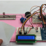
In this article, we will make a simple Buld A RFID Based Door Lock Security System using Arduino Nano. Step by step, we will see how this system is built, how it works, what components are needed, its circuit diagram, and complete working code.
This project is very useful because security has become an important part of our daily life, and technology can make it even stronger.
Here, we will use an Arduino Nano, RFID module (RC522), 16×2 LCD (without I2C), servo motor, buzzer, and a red LED.
Only the authorized RFID card will unlock the door, and unauthorized cards will be denied.
You can use this project in school projects, college final-year projects, science exhibitions, home door security, garage locking, and more.
A video tutorial for this project is also available on my YouTube channel Plasma Science. I will give the link at the end of this article so you can watch it if needed.
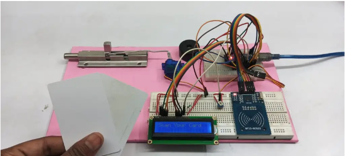
Table of Contents
RFID Based Door Lock Security System Works
When you bring an RFID card near the RFID Reader (RC522), it reads the unique ID (UID) of the card and sends it to the Arduino Nano.
- The Arduino checks if the scanned UID is authorized or not.
- If the card is authorized, the Arduino sends a signal to the servo motor, and the motor rotates to unlock the door.
- The LCD shows “Access Granted”.
- After a few seconds, the door locks again.
- If the card is unauthorized, the Arduino gives a signal to the buzzer and the red LED.
- The buzzer beeps,
- The red LED turns ON,
- The LCD shows “Access Denied”.
This way the system ensures that only registered cards can unlock the door.
Components Required For RFID Door lock Security System
- 1. Arduino Nano :- The main controller that processes the RFID data.
- 2. RFID Module RC522 :- Reads RFID cards and sends the UID to Arduino.
- 3. 16×2 LCD Display (Without I2C) :- Shows messages like “Access Granted”, “Access Denied”, etc.
- 4. Servo Motor :- Used as the lock—rotates to unlock and lock the door.
- 5. Buzzer :- Alerts when an unauthorized card is scanned.
- 6. Red LED (Optional) :- Glows when access is denied.
- 7. Jumper Wires & Breadboard :- Used for making all the connections.
RFID-Based Door Lock Security System Circuit Diagram & Connections
Circuit Diagram
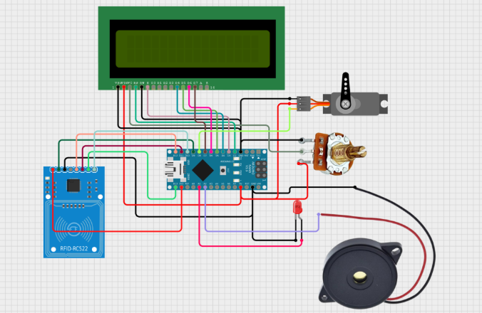
Pins Connections Explain
RFID Module (RC522) → Arduino Nano
- SDA → D10
- SCK → D13
- MOSI → D11
- MISO → D12
- IRQ → Not Connected
- GND → GND
- RST → D9
- 3.3V → 3.3V
16×2 LCD (Without I2C) → Arduino Nano
- RS → D7
- EN → D6
- D4 → D5
- D5 → D4
- D6 → D3
- D7 → D2
- VSS, RW, K → GND
- VDD, A → 5V
Servo Motor
- Signal → D8
- VCC → 5V
- GND → GND
Buzzer & LED
- Buzzer → D3
- Red LED (+) → D2
- Red LED (−) → GND
RFID Based Door Lock Security System Coding
How to Upload the Code in Arduino Nano
First, open the Arduino IDE software on your computer. After the IDE opens, go to the Tools menu and select the correct Board → Arduino Nano. Then choose the right Port where your Arduino Nano is connected.
Now copy the complete project code and paste it inside the Arduino IDE.
After that, click on the Upload (arrow) icon on the top bar.
The code will start uploading into your Arduino Nano.
Once the upload is done, your system is ready for testing.
#include <SPI.h>
#include <MFRC522.h>
#include <LiquidCrystal.h>
#include <Servo.h>

// Define RFID Module
#define SS_PIN 10
#define RST_PIN 9
MFRC522 rfid(SS_PIN, RST_PIN);

// Define LCD Pins
LiquidCrystal lcd(2, 3, 4, 5, 6, 7);

// Define Servo Motor
Servo doorLock;

// Define Components
const int redLED = A1;
const int buzzer = A0;
const int servoPin = 8;

// Authorized UID (Replace with your RFID tag UID)
byte authorizedUID[] = {0xC3, 0x56, 0x6C, 0xA9};

void setup() {
    Serial.begin(9600);
    SPI.begin();
    rfid.PCD_Init();

    lcd.begin(16, 2);
    lcd.print("Scan Your Card");

    pinMode(redLED, OUTPUT);
    pinMode(buzzer, OUTPUT);

    doorLock.attach(servoPin);
    doorLock.write(0); // Lock position
}

void loop() {
    if (!rfid.PICC_IsNewCardPresent() || !rfid.PICC_ReadCardSerial()) {
        return;
    }

    Serial.print("Card UID: ");
    bool isAuthorized = true;
    for (byte i = 0; i < 4; i++) {
        Serial.print(rfid.uid.uidByte[i], HEX);
        Serial.print(" ");
        if (rfid.uid.uidByte[i] != authorizedUID[i]) {
            isAuthorized = false;
        }
    }
    Serial.println();

    if (isAuthorized) {
        lcd.clear();
        lcd.print("Access Granted");

        digitalWrite(buzzer, HIGH);
        delay(200);
        digitalWrite(buzzer, LOW);

        doorLock.write(90); // Unlock door
        delay(3000);
        doorLock.write(0); // Lock door again
    } else {
        lcd.clear();
        lcd.print("Access Denied");

        digitalWrite(redLED, HIGH);
        for (int i = 0; i < 3; i++) {
            digitalWrite(buzzer, HIGH);
            delay(200);
            digitalWrite(buzzer, LOW);
            delay(200);
        }
        digitalWrite(redLED, LOW);
    }

    rfid.PICC_HaltA();
    rfid.PCD_StopCrypto1();
}
Door Lock System Code
RFID-Based Door Lock System Testing
✅ Step 1:
Power ON the system.
The LCD will show: “Scan Your Card”
✅ Step 2:
Bring an RFID card near the reader.
The RC522 will scan the UID and send it to the Arduino.
✅ Step 3:
If the scanned card is authorized:
- The servo motor unlocks the door
- The LCD shows “Access Granted”
- After a few seconds, the door locks again automatically
✅ Step 4:
If the card is unauthorized:
- The buzzer beeps loudly
- The red LED turns ON
- The LCD shows “Access Denied”
Everything resets automatically and waits for the next scan.
RFID-Based Door Lock System Video Tutoreal
how to make RFID door lock :- https://www.youtube.com/watch?v=HSLGVbhiNWw&t=12s
Conclusion
his RFID-Based Door Lock System is a smart, simple, and secure project that anyone can build using basic electronic components. It helps you understand RFID technology, Arduino programming, servo control, and LCD interfacing.
You can use this project in homes, offices, schools, labs, and garages to improve security.
Once you understand the basics, you can upgrade this system by adding features like:
- Logging card entries
- Adding more users
- Using an I2C LCD
- Connecting it with Wi-Fi
- Using a solenoid lock
This project is perfect for beginners and a great choice for science fairs, school projects, and final-year engineering projects. read More.
Build a Hand Gesture Controlled LED System (Arduino + Python) | Simple 5 Steps (2026)
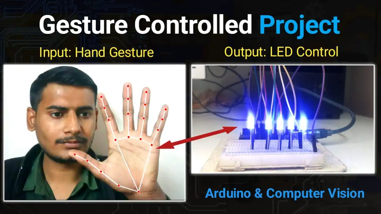
Imagine controlling the lights in your room without touching a single switch—just like Iron Man! In this project, we will build a Hand Gesture Controlled LED System using an Arduino Uno and Python.We will use Computer Vision (OpenCV and MediaPipe) to detect your fingers and send commands to the Arduino to turn LEDs ON or…
How to make a Radar system using Arduino and Ultrasonic Sensor
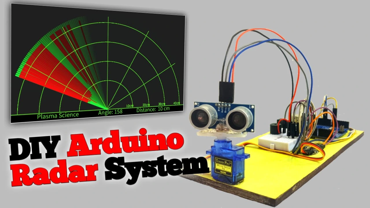
Hello friends, in this tutorial I will teach you how to build a radar system. I will use an Arduino, an ultrasonic sensor, andProcessing software. Processing software will be used to calculate the distance and angle of the scanning area. Even if you’re new to Arduino, you can easily build it. I’ve explained each step…
Why the vivo X300 Series Is a Must-Have in 2025: Features, Specs, and Prices

The Vivo X300 series has been launched in India on 2 December 2025. Many people were waiting for this phone, and now the company has finally released it in India after the global launch. This is exciting news for smartphone lovers and photography fans. In this series, Vivo has launched two models — Vivo X300…
Interstellar Object Explained: Origin, Speed, Latest News, Real Images & Complete List of Interstellar Objects (2025 Update)

Discover what interstellar objects are, how they travel, and why 3I/ATLAS is trending in 2025. Full list of 1I ʻOumuamua, 2I Borisov, and 3I ATLAS explained. If you are curious to know what these cosmic visitors are, how fast they travel, and how many such objects we have found in our Solar System, then this…
Best Gaming Phones Under ₹20,000 in India

Find the best gaming phones under ₹20,000 with performance tests, display quality, battery backup, camera review, and gaming FPS for 2025. Choosing a gaming phone under ₹20,000 is very difficult today because the market has too many options. Some phones are fast, some are overhyped, and finding the right one becomes confusing. That’s why I…
How To Buld A RFID Based Door Lock Security System
In this article, we will make a simple Buld A RFID Based Door Lock Security System using Arduino Nano. Step by step, we will see how this system is built, how it works, what components are needed, its circuit diagram, and complete working code. This project is very useful because security has become an important…


video tutorial open nahi ho rha bro